We have Canadian Jensen owner to thank for Patrick Hiron for:
"THE BOY'S WONDERBOOK OF WINDTONE HORNS"
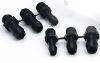
Wind
tone horns, developed by Lucas in the 1930s, were originally fitted to
high end motor cars. Two separate horns, a high and a low note, as Lucas
said, "To give a Pleasing Harmonious Chord which remains constant
under all conditions
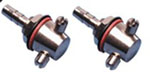
As time
went by these horns went down market and were fitted to just about every
British car in from the 1950s onwards. There are many variations in
Windtone horn design and construction, as time went by their materials
and construction became increasingly cheaper. However all Windtones work
on the same principle.
The 1938
Lucas catalogue says that:
"The
note is produced by the excitation of a column of air, just as in a
concert instrument - - the pitch and character of the sound of the
instrument is decided by the correct acoustic shape and scientifically
determined dimensions of the trumpet. For these reasons the note cannot
vary
The
"excited column of air is produced by a vibrating diaphragm actuated by
a powerful electromagnet.
Problem
areas:
Windtone
horns live a neglected life, out of sight and out of mind, until they
fail.
There
are three potential problem areas, the horn mounting points, wiring and
earth connections, and the horn internals
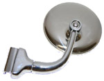
Horn
mounting points:
My Lucas
catalogue has a full page of Windtone mounting brackets. These vary from
elegant laminated spring steel mounts to solid agricultural looking
lumps of steel.
They are
all designed to absorb the considerable vibration produced by the horns.
Poorly mounted horns can produce off sounds and vibration in the
structure of the car, so check that the horns are solidly mounted.
Wiring
and earth connections:
Interceptor horns are wired through relays. The low power side of the
relay is earthed through the horn button, this pulls in the relay making
a high power connection feeding power to the horn electro magnet and
then to earth, completing the horn circuit.
First
check the fuses are intact and that the fuse holder terminals are tight
and clean before moving on to check the power wiring. The horns use a
great deal of power, so it's no use pushing the horn button and using a
multi meter to confirm there is power at the inlet connection to the
horn and to earth. You need a hefty load to replace the horn when
checking out the capacity of the wiring.
I
disconnected the horn and used an old head light wired across the horn
power feed, first directly to earth and then as a connection between the
power feed and the horn's earth wire. This shows whether both the power
feed to the horn and the wire connecting the earth terminal on the horn
to ground are OK.
The
earth connection to the car is often poor. Cleaning this connection
often solves horn problems. If the power circuit and ground connection
are sound the horn itself is faulty.
If the
fuses are OK and there is no power to the horns then you need to work
back through the horn circuits to find the problem. The most likely
problem areas are the connections on the relays which often need to be
cleaned, or the relays themselves.
Horn
internals:
If the
horns have to be worked on, remove them from the car and work on them in
comfort in the garage. Work on one horn at a time, keeping the other
horn as a reference. Mount the horn in the vice; bring in the battery
and some heavy wire to connect power to the horns.
The "Column
of excited air '' is produced by a vibrating metal diaphragm which
is moved upwards by a hefty electro magnet energised by a make and break
switch in the horn's internal wiring. The electromagnet attracts the
diaphragm. The diaphragm in turn moves a rod which opens the make and
break switch contacts, cutting off power to the electro magnet. The
diaphragm then returns to its rest position, the rod drops, and the
switch contacts close, powering the solenoid and flexing the diaphragm.
The diaphragm, electro magnet and the make and break switch must all is
in good condition, so remove the horn's top cover and look inside.
Windtone
horns generate a great deal of heat in operation. I found out the hard
way that it's not a good idea to use penetrating oil or flammable
solvents to clean up the horn internals. Spray cans of brake cleaner,
and computer cleaner "air are a much safer bet.
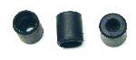
Diaphragm:
The
diaphragm is solidly fixed to the bottom trumpet section by either
rivets or 2 BA nuts and bolts, depending on Joe Lucas's cost
accountant's whims. Clean off the top face of the diaphragm using an air
line or a spray can of air. DO NOT separate these two components "to see
what's inside You may have to replace loose rivets or nuts and bolts,
or even strip the horn if the diaphragm is cracked or rusted out .If you
separate the diaphragm be careful not to damage the thin rubber gasket .
Electromagnet:
It's
easy to check the electromagnets heavy wiring using a multimeter across
the inlet and outlet terminals
If the
diaphragm and electromagnet coil are OK the problem lies with the make
and break switch. Many horn problems result from unhappy attempts to
tune the horn by "adjusting the switch.
Make and
break switch:
This is
typically Lucas, Rube Goldberg inspired confection. The contacts are
often misaligned, loose, dirty and burned. They should be tightly
screwed down, and aligned and clean. It possible to align the contacts
by fiddling with the tiny screws holding them in place and clean them in
situ with 600 wet and dry moistened with brake cleaner. If this doesnt
work you will have to strip the contacts out and either polish them on
oil stone or replace them. I have found NOS Windtone contacts on E Bay.
Be
warned! The switch is a glorious mix of tiny BA screws and bits of
[Mica, Tufnol,] insulation and sproingy metal. This why you should
repair one horn at a time, you have an unmolested model for reference if
things go pear shaped. If you have to strip out the contacts take
digital pictures at each stage and lay out the parts in sequence.
Stripping out the switch will let you clean up the actuating rod buried
in the horn internals. It's worthwhile pulling out the rod and polishing
it with chrome cleaner, and then flushing the recess it lives in at the
diaphragm. The objective is to have the rod move cleanly. Do not be
tempted to help it along with any sort of lubricant.
By now
you should have confirmed that:
1.
The diaphragm is in good condition and is solidly attached to the
trumpet base of the horn
2.
The electromagnet's windings are in good condition
3.
The
actuating rod is clean and moves freely
4.The
contacts are polished and centred.
5.The
switch is properly installed and bolted firmly into place.
The last
job is to set the make and break contacts. You will need: a multimeter,
a pair of very thin 3BA open ended spanners [I had to grind down the
faces of two old spanners to make suitable tools] and a great deal of
patience.
The horn
depends on the make and break switch operating cleanly, snapping
decisively between open and closed. If it is maladjusted there will be
either a dead silence or a "mad MIG welder display of arcing.
The
contacts must be adjusted so that the switch is just closed with no
power at the horn. Use the multimeter to adjust the points so that they
just break, then turn the adjuster half a turn so that the contacts are
fully closed. Use the lock nut to lock the adjuster screw in place.
Test the
horn on the bench using heavy wiring before putting it back on the car